NEW Dayton Audio MA1280 8 Input 80W X 12 Channel Class D Amplifier


The Dayton Audio MA Series multi-channel amplifiers deliver the perfect balance of power, efficiency, flexibility, and reliability. Featuring both global and individual channel inputs, these amplifiers can be configured for a wide range of applications. Their efficient, lightweight Class D design keeps energy consumption low without compromising on output performance.
Key Features
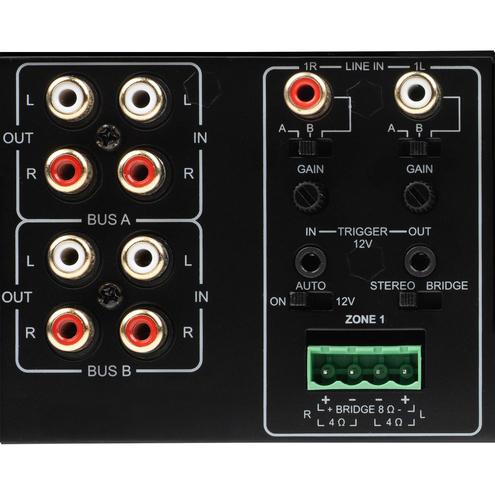
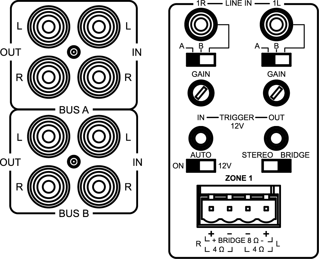
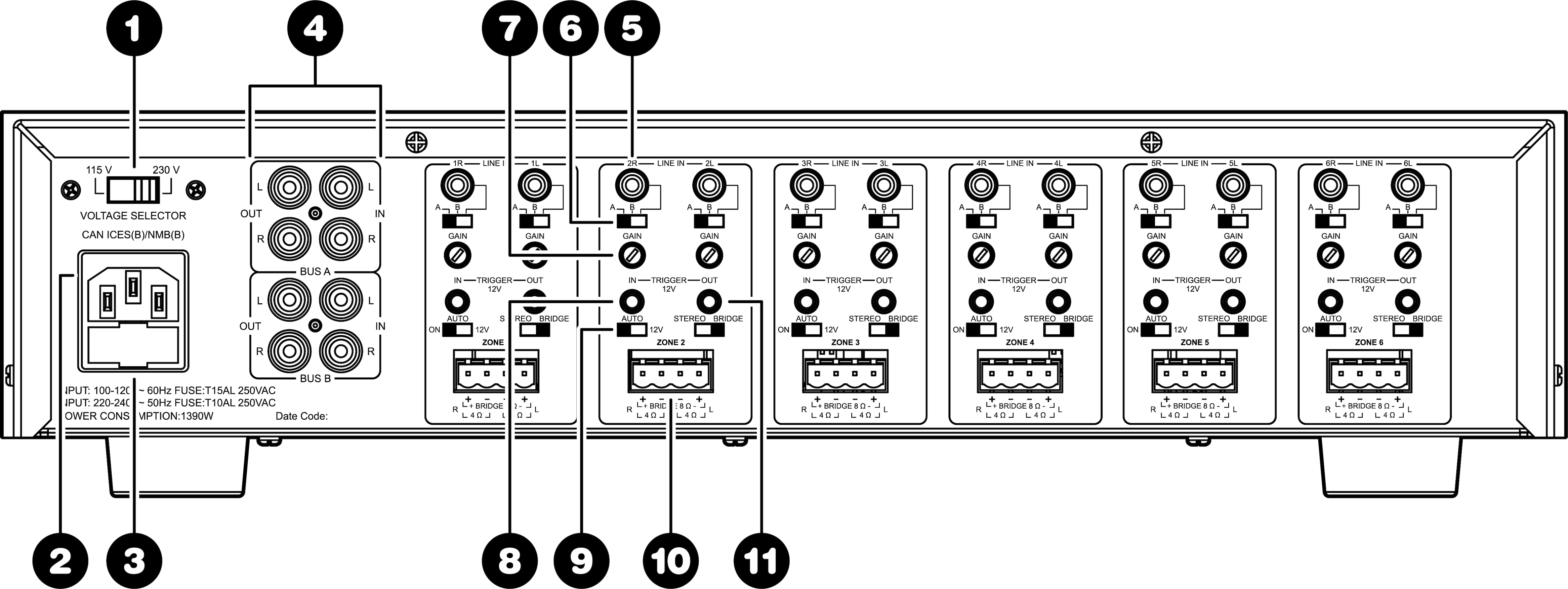
- Powerful Multi-Channel Amplification – 12 Class D channels delivering 80W RMS per channel at 8 ohms or up to 160W per zone in bridged mode, perfect for driving whole-home or theater systems
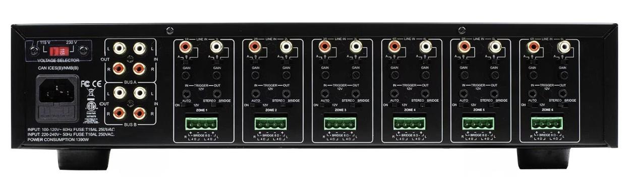
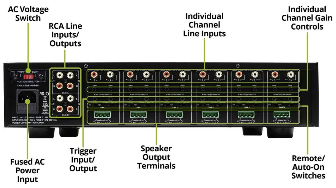
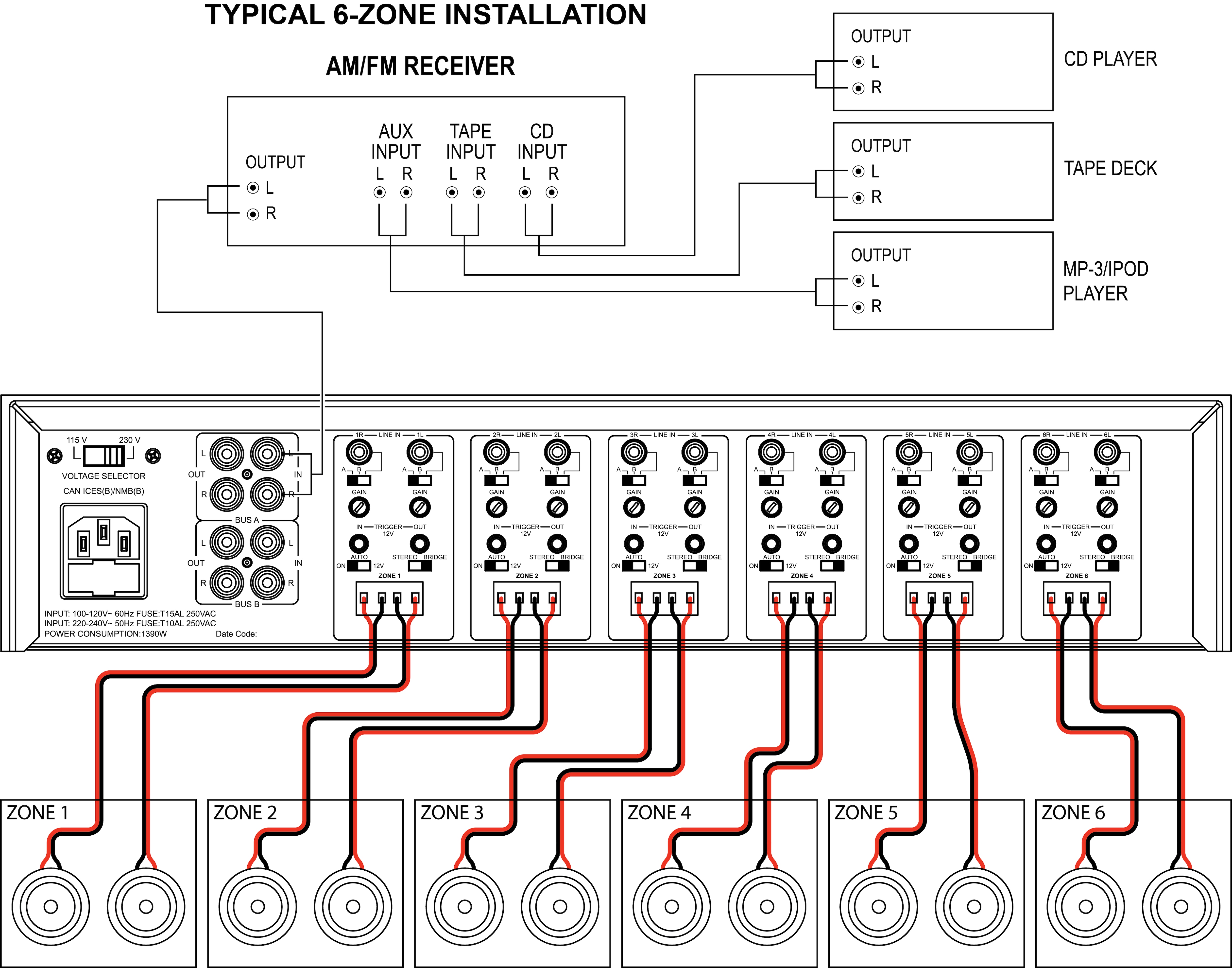
- Flexible Audio Routing – Use 8 independent line inputs, 2 stereo bus inputs, or a combination of both to send music exactly where you want it
- Whole-Home or Single-Room Use – Distribute audio to 6 zones for up to 6 rooms, or with an appropriate processor, power a full multi-channel home theater setup with ease.
- Smart Installation Features – 2RU rack-mountable design with removable ears, manual or auto-on signal sensing, and 12V trigger input for automation systems
- Clean, Detailed Sound – Wide 20Hz–20kHz frequency response, high 106 dB signal-to-noise ratio, and less than 1% THD for professional-quality audio
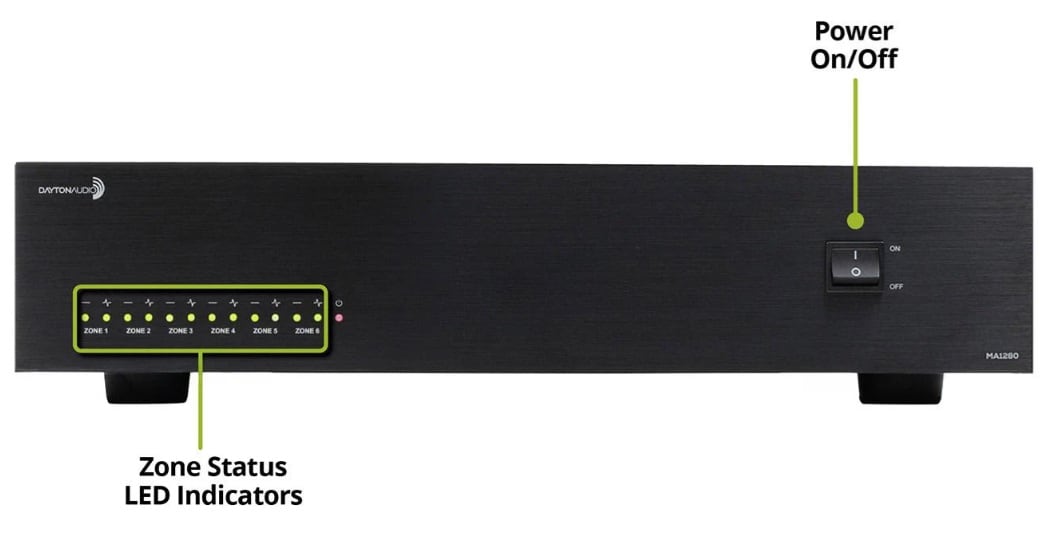
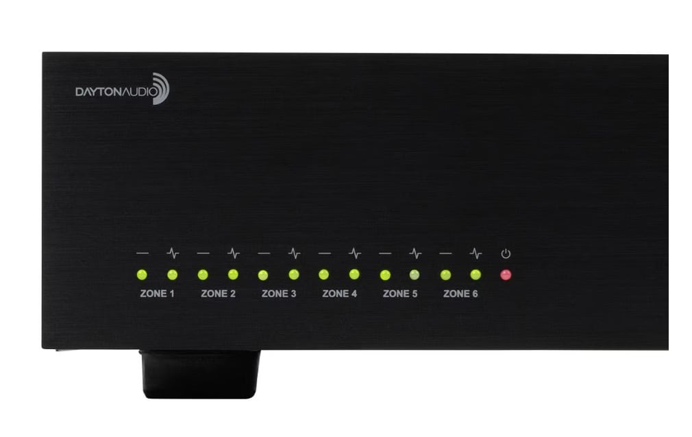
- Zone Status at a Glance – Bi-color LEDs show each channel pair’s operational status for quick troubleshooting
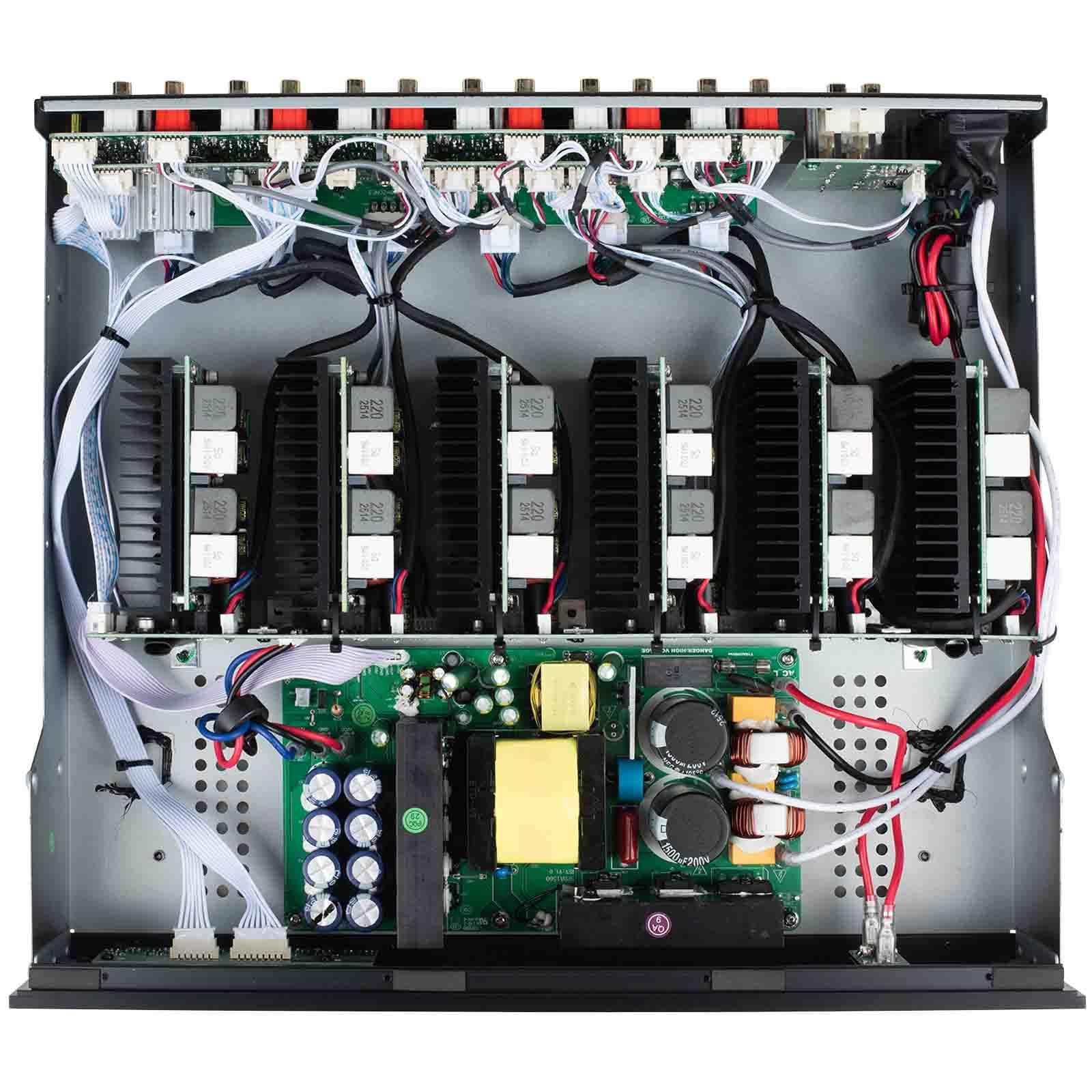
- Efficient & Reliable – Lightweight Class D design runs cool while delivering consistent, dependable performance in demanding setups
Similar items that may interest you:
See all items in Multi-Zone Amplifiers

NEW $849.98
+ FREE SHIPPING
MSRP: $973.99
Bulk Pricing
In Stock
Get Notified When Available
We'll send you an email when Dayton Audio MA1280 8 Input 80W X 12 Channel Class D Amplifier is back in stock or available for preorder.
Order in the next 5 hr 52 min to ship today. Details

Free Shipping available on orders over $99.00 in the US. Details
60 Day No Hassle Return Policy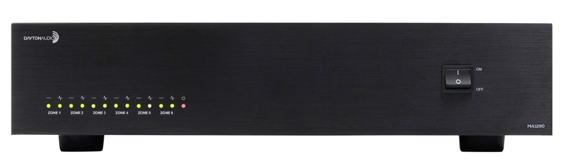
 California Prop 65