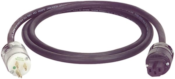
IEC Power Cable Assembly
Warning: To prevent possible electrical shock, make sure that the cable assembly is not connected to power prior to completing the entire cable assembly sheet procedure.
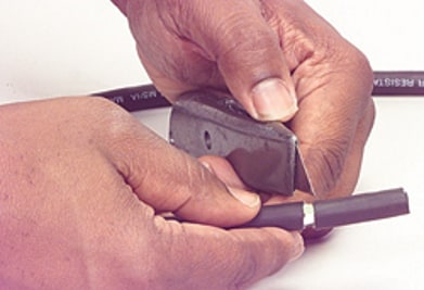
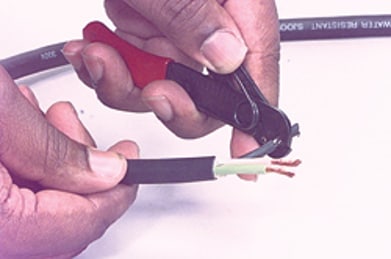
Step 1:
Using a utility knife carefully cut off 1-1/4" of the outer insulation without slicing or damaging any of the interior conductors. Trim off the white dielectric pieces.
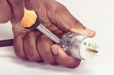
Step 2:
Prior to terminating the plug onto the cable separate the plug assembly from the bottom housing by loosening the two housing screws on the face of the plug.
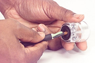
Step 3:
Loosen the two cord clamp screws on the side of the housing base and proceed to insert the cord end through the housing base hole. Make sure that the cord clamp assembly is open enough to except the cable. (Note: the cord clamp inside the housing base will only except a 14/3 S or 12/3 S cord with an outer diameter no larger than ½". Its is necessary to remove the cord clamp assembly for cables with outer diameters larger than ½".
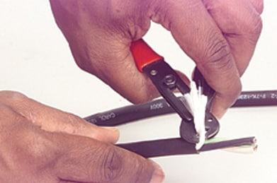
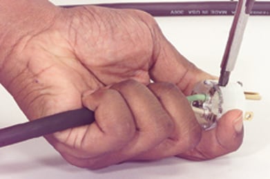
Step 4:
Using a wire stripper remove ½" of insulation from the three conductors and insert the wires into their proper terminal pockets. Its is very important to make sure that each wire goes into its proper terminal pocket completely with no visible stray wires exposed. The green wire must go into the ground terminal pocket marked "GR" or colored green. The white wire must go to the terminal marked "N" or silver colored terminal. The black wire must go to the terminal marked "L" or brass or black colored screw.
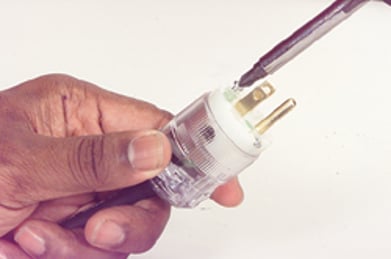
Step 5:
Gently slide the device housing over device body. Note that both pieces are keyed and align together. Tighten the facial screws and then tighten the cable clamp to complete cable connector assembly end. Make note to only tighten down the cable clamp to approximately 8-10 in-lbs. torque.
Step 6:
Perform steps 1-5 for other side of cable assembly.