Crossover Component Selection Guide
Using the charts
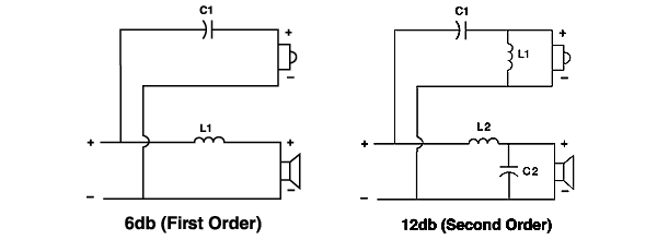
The chart below is for calculating 6dB and 12dB crossovers. For higher crossover points than those shown, simply move the decimal point to the right one place to match the new frequency, find the capacitor and inductor values and move their decimal point one place to the left. For example: If you desire a high-pass crossover frequency of 50 Hz for a 12 dB crossover for 8 ohms, find the 500 Hz listing. Locate capacitor and inductor values and move their decimal one place to the right. The correct values would then be 36.01 mH and 281.35 µF. Example 2: if you desire a low-pass crossover frequency of 50 for a 6 dB crossover for 4 ohms, find the 500 Hz listing. Locate the inductor value and move it's decimal to the right, making it 12.7 mH.
| High Pass Crossover Frequency | 6 dB/octave | 12 dB/octave | ||||
| 4 Ω | 8 Ω | 4 Ω | 8 Ω | |||
| C1 in μF | C1 in μF | L1 in mH | C1 in μF | L1 in mH | C1 in μF | |
| 500 ㎐ | 79.60 | 39.80 | 1.801 | 56.270 | 3.601 | 28.135 |
| 700 ㎐ | 56.86 | 28.43 | 1.286 | 40.193 | 2.572 | 20.096 |
| 1,000 ㎐ | 39.80 | 19.90 | 0.900 | 28.135 | 1.801 | 14.067 |
| 1,500 ㎐ | 26.53 | 13.27 | 0.600 | 18.757 | 1.200 | 9.378 |
| 2,000 ㎐ | 19.90 | 9.95 | 0.450 | 14.067 | 0.900 | 7.034 |
| 2,500 ㎐ | 15.92 | 7.96 | 0.360 | 11.254 | 0.720 | 5.627 |
| 3,000 ㎐ | 13.27 | 6.63 | 0.300 | 9.378 | 0.600 | 4.689 |
| 3,500 ㎐ | 11.37 | 5.68 | 0.257 | 8.039 | 0.514 | 4.019 |
| 4,000 ㎐ | 9.85 | 4.98 | 0.225 | 7.034 | 0.450 | 3.517 |
| 4,500 ㎐ | 8.84 | 4.42 | 0.200 | 6.252 | 0.400 | 3.126 |
| 5,000 ㎐ | 7.96 | 3.98 | 0.180 | 5.627 | 0.360 | 2.813 |
| Low Pass Crossover Frequency | 6 dB/octave | 12 dB/octave | ||||
| 4 Ω | 8 Ω | 4 Ω | 8 Ω | |||
| L1 in mH | L1 in mH | L2 in mH | C2 in μF | L2 in mH | C2 in μF | |
| 75 ㎐ | 8.49 | 16.99 | 12.00 | 375.132 | 24.00 | 187.566 |
| 100 ㎐ | 6.37 | 12.74 | 9.00 | 281.349 | 18.00 | 140.674 |
| 150 ㎐ | 4.25 | 8.49 | 6.00 | 187.566 | 12.00 | 93.783 |
| 200 ㎐ | 3.19 | 6.37 | 4.50 | 140.674 | 9.00 | 70.337 |
| 250 ㎐ | 2.55 | 5.09 | 3.60 | 112.540 | 7.20 | 56.27 |
| 300 ㎐ | 2.12 | 4.25 | 3.00 | 93.783 | 6.00 | 46.891 |
| 350 ㎐ | 1.82 | 3.64 | 2.572 | 80.385 | 5.145 | 40.193 |
| 400 ㎐ | 1.59 | 3.19 | 2.251 | 70.337 | 4.502 | 35.169 |
| 450 ㎐ | 1.42 | 2.83 | 2.00 | 62.522 | 4.00 | 31.261 |
| 500 ㎐ | 1.27 | 2.55 | 1.80 | 56.270 | 3.60 | 28.135 |
| 700 ㎐ | 0.91 | 1.82 | 1.286 | 40.193 | 2.572 | 20.096 |
| 1,000 ㎐ | 0.637 | 1.27 | 0.900 | 28.485 | 1.804 | 14.067 |
| 1,100 ㎐ | 0.579 | 1.16 | 0.818 | 25.577 | 1.637 | 12.789 |
Tolerances
When looking for capacitors and inductors in our listings, keep in mind that the tolerances of the components can help simplify your search. For example: The calculation chart finds 281.35 to be the exact capacitor value for the above crossover. If you're looking through the Non-Polarized Crossover Capacitors, their tolerance is 10%. This means that the actual measured value of each capacitor is within 10% of the listed value, in this case ±28 µF. So, adding 250 µF and 33 µF in parallel to achieve 283 µF, considering the tolerance, will put them somewhere between 255 and 311 µF, which is suitable for the application. For example 2, if you're looking in the 18 gauge, Perfect Layer Wound Air Core Inductors, their tolerance is ±2%. The calculated value of 12.7 mH could be suitably achieved using a 12.00 mH inductor, whose 2% tolerance puts its actual value between 11.76 and 12.24.
Combining Components To Achieve Needed Values
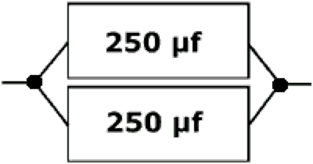
If you are unable to find larger component values, components may be added together to yield the desired values. To add capacitor values, they can be connected to each other in parallel . For example, if a value of 500 µf is needed, two 250 µf caps can be connected such that both sets of leads are connected, as is shown below:
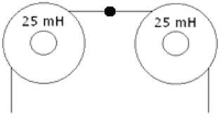
To add inductor values: though not commonly done, they can be added in series . For example, if a value of 50 mH is desired, you can add two 25 mH inductors such that the leads are connected as shown below:
Mounting components to the PC board is simple. Orient the components on the board so they match the diagram, making sure the component leads are directed properly to match their soldering points. Both crossovers on the board use a coil, and should be arranged so they cannot affect each other (mutual inductance). Do this by mounting one standing up like a tire on a car, the other lying flat. Then simply use hot melt glue to securely attach the components to the board. After the components are secure, solder the component leads at their appropriate soldering points on the board.