Automotive Relays
Common Relay Pin Configuration (Bosch-type)
Overview
Relays are widely used in electrical applications when a large current/voltage needs to be switched on and off by a low power control circuit. An example of this is in motor vehicle headlight circuits. If the headlight switch on the dash controlled current to the headlights directly, a switch capable of carrying sufficient power to operate the lights would have to be used in the dash. It would also be necessary to connect the switch with wire of a sufficient gauge to transfer the power from the electrical system to the lights. A relay is a safer and less expensive way to operate a circuit that carries power, allowing control of up to 30 or 40 amps with a .15 amp control circuit. At 12 volts, 40 amps of current translates to 480 watts of power.
A relay consists of a set of switch contacts and a switching mechanism. This mechanism is simply an electromagnet. A metal core is wrapped with a coil of fine copper wire; the core becomes magnetized when voltage is applied to the coil. One end of the core is held within close proximity to one side of the metal switch contacts. When energized, the magnetized core attracts the metal contact and pulls it into contact. In doing so, the switch contacts close or "toggle". When the coil is de-energized, the magnetism in the core dissipates and releases the metal contact. The switch contacts then spring back to their original position.
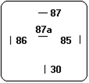
The diagrams below are a schematic representation of a standard automotive relay as originally designed by Bosch. Pins 85 and 86 are the connections for the electromagnet's coil. One will be grounded and the other connected to 12 volts. Either pin can be wired through a mechanical switch (as in the headlights application), or possibly by an electronic circuit containing ICs and/or transistors to switch the voltage on and off. In this application, a diode is often wired in parallel across 85 and 86 to help protect the IC or transistor from current transients created by the coil.
Pins 87, 87a, and 30 are the connections for the switch contacts, and are generally rated for at least 30 amps. This switch is a single pole, double throw type, or SPDT. Pin 30 is the "pole", which can "throw" to either of the other two contacts. In its normal state, the pole is connected to pin 87a. When energized, the relay toggles so that the connection is broken between the pole and 87a and completed to pin 87. So depending upon how the switch is wired, it can open an electrical circuit as easily as close the circuit!

Relay at rest

Relay energized
Connections
The terminals of a relay are defined as follows:
- 30 is the pole or common.
- 87a is the normally closed connection.
- 87 is the normally open connection.
- 85 is connected to 12 volts or ground and may be switched.
- 86 is connected to 12 volts or ground and may be switched.
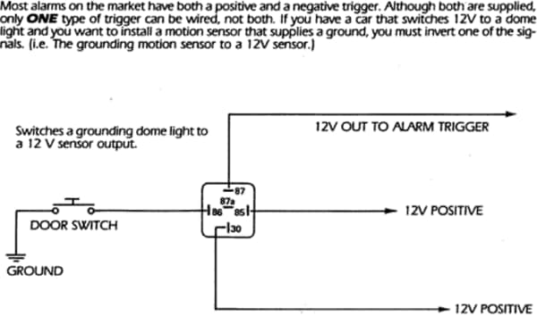
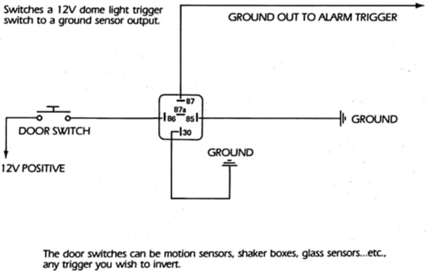
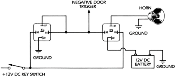
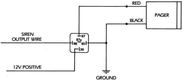
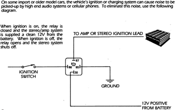
Relays are very versatile and can be wired in a number of ways to be made to act in a certain way. Several of these circuits are shown below. For more information on using relays and other relay specifications, refer to any first-year electronics text book.

Disclaimer
This information provided as an option to those who wish to use it. It is recommended only to those who have some familiarity with such practices and/or audio electronics in general. Parts Express is not responsible for any damages sustained from mishandling of products or incorrect interpretation of this information. Please refer all questions or concerns to our Technical Staff.