We use cookies to provide the best possible customer experience across this site, through third party ads and analysis of web data. By continuing you agree to our use of cookies and our overall privacy policy.
BASH's patented 300 watt Subwoofer Amplifier technology was developed to offer extreme amounts of power with an efficient operation that escapes most traditional amplifier designs.
Key Features
High power output in a compact, lightweight design
Speaker and line level inputs for connection to any stereo
Limiting circuit prevents audible clipping and protects woofers
Excellent choice use in new designs or even retrofitting existing subwoofers
Bash 300S Digital Subwoofer Plate Amplifier 300W RMS
BASH patented amplifier technology was developed to offer extreme amounts of power without the wasted heat and energy of traditional amplifier designs. Add to this an intelligent circuit design, and you get benefits such as extremely low distortion and high signal to noise ratios. The combination of clean output and high power makes the BASH amplifiers some of the best sounding subwoofer amplifiers on the market. Features: 50 to 150 Hz low-pass crossover, 0° or 180° phase, line level inputs, speaker level inputs, LFE input, master on/off switch, auto on.
Specifications: • 300 watts RMS @ 0.5% THD into 4 ohm load • Signal to noise ratio: 105 dB (A-weighted) • Line-in and high-level in crossovers: Adjustable 50 to 150 Hz, 12 dB/octave low-pass crossover • LFE-in crossover: Fixed 330 Hz, 12 dB/octave low-pass crossover • Power requirements: 120 VAC, 60 Hz • Dimensions: 11" W x 7" H x 3-1/2" D • Cabinet cutout: 9-3/4" x 6"
Connections and ControlsOn/Auto/Standby Switch Set to Auto to allow the amplifier to automatically turn on and off as a signal is sensed. Set to On for "always on" mode. Set to "Standby" for standby mode. Phase Switch 0° or 180° selectable, 0° is normal phase, 180° will reverse the polarity of the subwoofer output Volume Control Adjusts the output level of the amplifier Freq Sets the low-pass crossover frequency, adjustable from 50 to 150 Hz Line Level Inputs For connection to a full-range stereo line level signal, use the left and right line level inputs; the on-board low-pass crossover will be in effect. For connection to the subwoofer out on a home theatre receiver, use either the LFE input to bypass the internal crossover or the Left or Right input for additional crossover flexibility. Hi Level Inputs Allows the connection of the amplifier to a speaker level output from a stereo amplifier or receiver AC Mains Input Fused IEC input with 3 amp 250V GMA-style fast blow fuse; accepts standard male IEC cord On/Off Switch Turns master power on and off
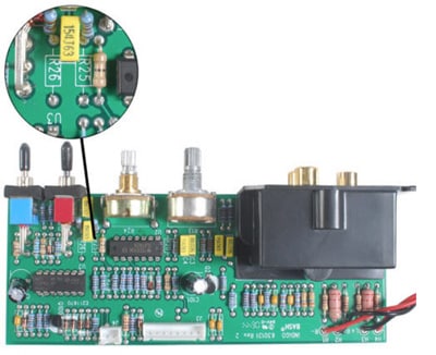
Modifying Bass Boost
1. Locate R26 and R25 on the pre-amp board, the default values are R26=30K and R25=120K. R26 and R25 are located on the small vertical PC board adjacent to the phase reversal switch.
2. Remove the existing resistors by using a low wattage soldering iron and desoldering braid. Be careful not to apply too much heat to the PC board traces.
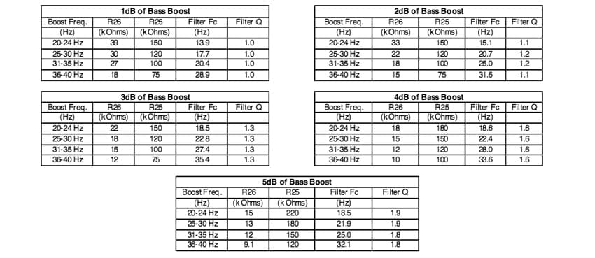
3. Using the charts below, determine the proper resistor values to achieve the desired boost. New resistors can be any wattage 1/4 or greater, but 1/4 will physically fit best. Note: values are in k Ohms.
4. Install the new resistors and solder in place making sure you put the correct resistor in the proper location.


 California Prop 65